"We installed guarding" is not the same as "we can prove it works"
Plenty of machines on Victorian factory floors have guards, interlocks, light curtains and an e-stop on every station, and no evidence at all that any of it performs to the level the risk demands. The devices are fitted. Whether the safety function actually stops the hazard, in every mode, with a fault present, in the time the safeguarding distance assumed — nobody has tested, and nobody has written it down.
Validation is the step that closes that gap. It turns "we put guarding on it" into a documented, defensible statement that each safety function has been assessed, verified against the required performance level, tested and signed off.
It's also the step most often skipped, because it's the one that needs a competent engineer rather than an installer.
What we check
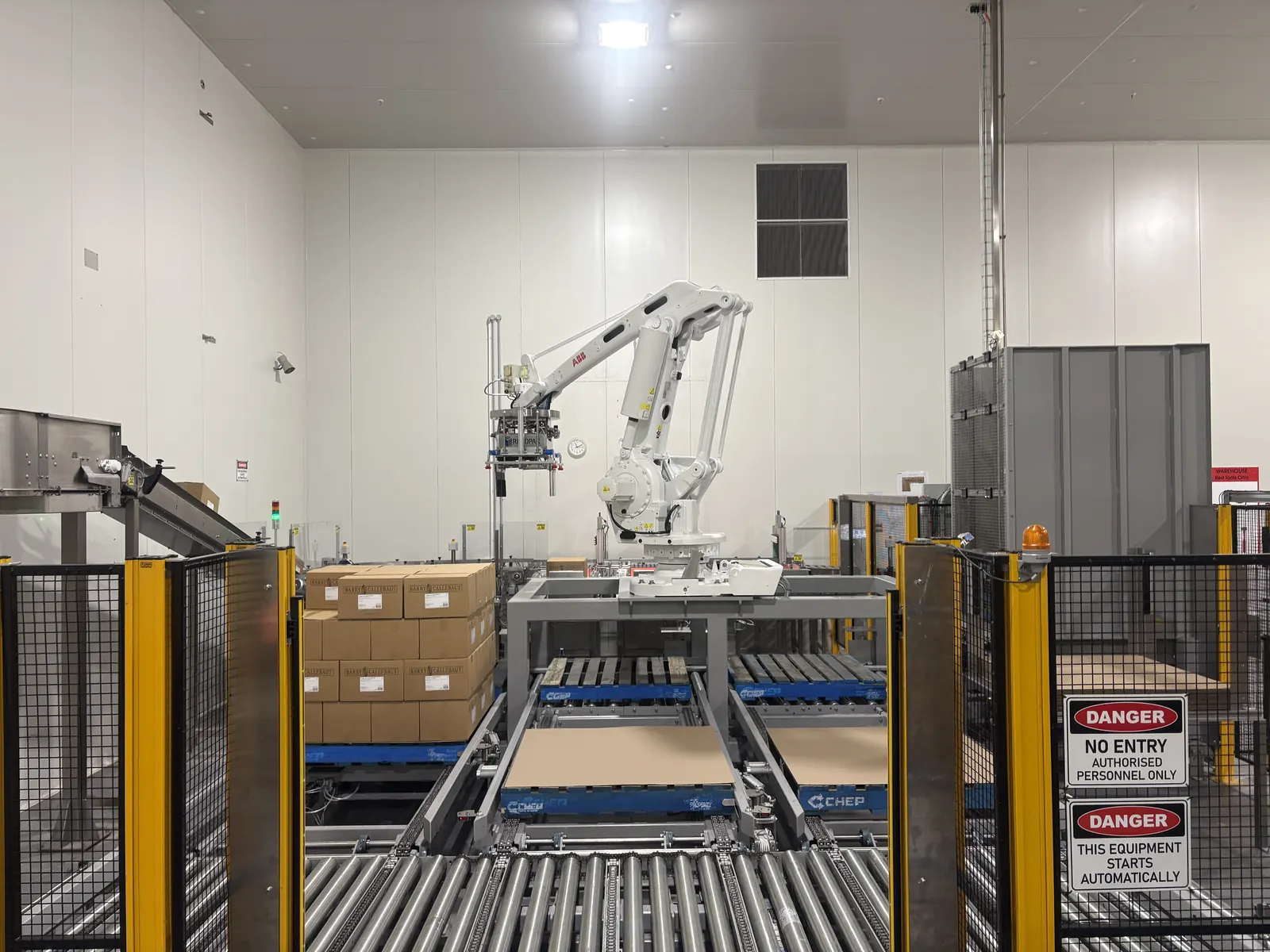
A risk assessment tells you what's dangerous. Validation asks a narrower question: does each safety function actually do what the risk demands of it, in every operating mode, with a fault present?
For each safety function we work through:
- What the function protects against — what triggers it, what it acts on, and whether that matches the hazard identified
- Performance level achieved — calculated from the installed architecture, and compared against the level the risk requires
- Response and reaction times — what the function actually achieves, which is what safeguarding distances depend on
- Behaviour on fault — what the machine does when a device, channel or output fails, and whether the fault is detected, latched and annunciated
- Operating modes — production, setup, jog, clean-down and maintenance each have different access needs and often different safety functions
- Reset, restart and muting conditions — including where a manual reset is required and where automatic restart is prohibited
- Interfaces with the standard control system — what the safety layer commands, and what the process PLC is allowed to influence
Performance level verification
Specifying a required performance level is straightforward. Proving the system you've built actually achieves it takes calculation.
We verify achieved performance level (PL) against required performance level (PLr) to AS/NZS 4024.1503 / ISO 13849-1 for each safety function, working through the full chain — input device, logic, output device — rather than assuming a rating from a supplier's brochure. That means:
- Architecture category (B, 1, 2, 3 or 4) — single or dual channel, and whether faults are detected
- MTTFd — mean time to dangerous failure for each channel, from manufacturer data or, for mechanical components, from operating cycles
- Diagnostic coverage (DC) — how much of the dangerous failure rate the system's own diagnostics actually detect
- Common cause failure (CCF) — scored against the standard's checklist, because two channels sharing a cable, a supply or an environment aren't as independent as the block diagram suggests
- Exclusions and assumptions — documented, so the calculation can be reviewed rather than taken on trust
The common failures we find are unglamorous: a Category 3 architecture undermined by a single-channel output, a safety relay correctly wired to a contactor with no feedback loop, or a PL d claim resting on a device that was never rated for it. These only surface when someone does the arithmetic.
Functional safety validation
Verification is the calculation. Validation is the test — every safety function, on the actual machine, against the SRS.
- Each safety function triggered by every means that should trigger it, in every operating mode
- Fault injection — channels opened, shorted and cross-connected to confirm the system detects the fault and goes to a safe state, rather than quietly losing redundancy
- Reset, restart and mode-change behaviour checked against the specification, including the cases that should not allow a restart
- Muting and blanking sequences tested for the ways they can be defeated, not just the way they're meant to work
- Confirmation that the machine reaches a genuinely safe state — stored energy, gravity-loaded axes, pneumatic and hydraulic residual pressure, and coasting inertia all included
- Every test recorded with the expected result, the observed result and a pass or fail
A safety function that works on the bench and fails during changeover has not been validated. Testing in the real operating modes is the entire point.
Safeguarding evaluation
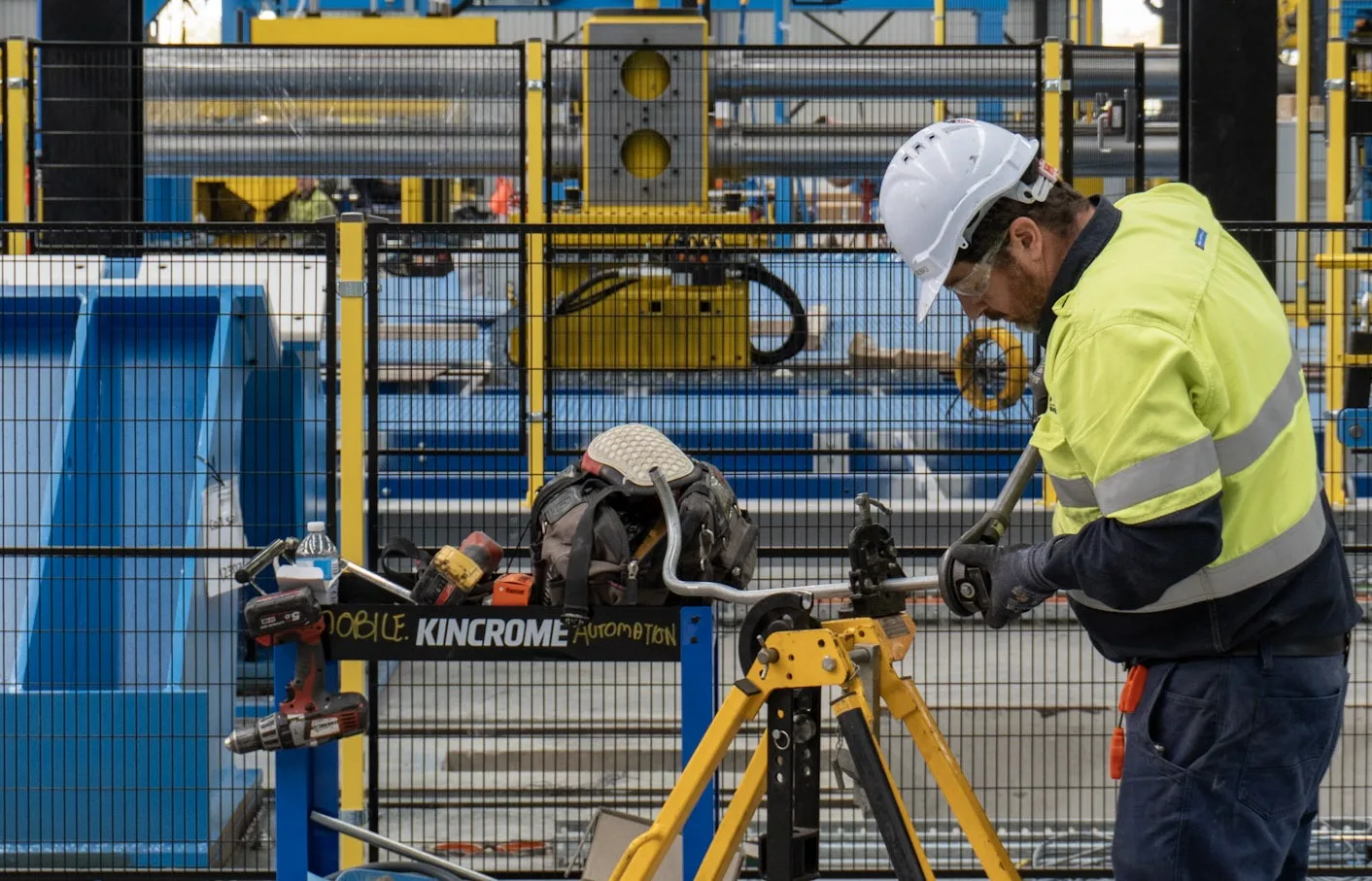
Before anything is specified or tested, the safeguarding that is already fitted has to be assessed against the hazards it is meant to control. A safeguarding evaluation looks at what is installed — fixed and interlocked guards, light curtains, area scanners, two-hand controls, e-stops and trip devices — and asks whether each one is the right measure, in the right place, for the risk it is covering.
- Whether the selected safeguard suits the hazard, the access frequency and the operating mode it has to work in
- Whether guards are positioned, fixed and constructed so they cannot be reached over, under, around or through
- Whether interlocks can be defeated in a foreseeable way, and whether the device type and mounting resist that
- Access points that are safeguarded on paper but bypassed in practice during setup, clean-down or fault clearing
- Gaps where a hazard has no safeguard at all — often on the maintenance side of a machine rather than the operator side
The evaluation is what tells you whether the existing arrangement can be validated as-is, or whether it needs to change first. It is also the point at which most of the practical findings appear.
Safeguarding distances and stopping performance
Light curtains, area scanners and interlocked gates are positioned on the assumption that the machine stops before a person can reach the hazard. That calculation depends entirely on the overall stopping performance of the machine — and on most machines, the number used is the one from the original design.
Real stop times drift. Brake wear, worn couplings, changed inertia from new tooling, a drive replaced with a different deceleration ramp, a safety relay swapped for one with a longer response time — all of it adds milliseconds, and milliseconds are millimetres of safeguarding distance.
We calculate the minimum safeguarding distance each device requires and check it against where that device is actually mounted, using the stopping performance recorded for the machine. Where the installed position does not satisfy the calculated distance, the finding comes with the fix — reposition the device, add a brake, reduce approach speed or change the stopping method.
Where the only stopping figure available is the original design number and the machine has since been modified, worn or re-tooled, we say so rather than calculate on a number we cannot stand behind. That finding calls for the overall stopping performance to be measured on the machine before the safeguarding distance can be relied on — and until it is, the distance should be treated as unverified.
The documentation pack
Validation only counts if it's written down. You receive a file that stands on its own:
- Performance level calculations with the inputs, assumptions and source data shown
- Safety circuit schematics and device schedules as installed
- Validation test plan and completed test records, with results and sign-off
- Safeguarding distance calculations, and the stopping-performance figures they rely on
- Register of any residual risks and the information-for-use they require
- Recommended periodic re-validation and proof-test intervals
That pack is what you hand to a WorkSafe inspector without a scramble, what an insurer or a customer's auditor asks for, and what your own maintenance team needs when a safety device fails at 2am and someone has to decide whether the machine can run.
TÜV-certified engineers
Our machine safety work is led by engineers with TÜV functional safety certification. Performance level calculations and validation sign-off are engineering judgements, and it matters who made them. Certified competency means the calculation, the test plan and the sign-off were produced to an internationally recognised standard — not to a supplier's selection tool, and not to a best guess.
Validation for machines we didn't build
A large share of our validation work is on equipment somebody else supplied: imported machinery with a compliance declaration written for another market, integrator-built cells, and guarding fitted by a contractor who wasn't asked to validate it.
We'll assess what's actually installed, write the SRS if one was never produced, verify the achieved performance level, test it and tell you plainly whether it passes. If it doesn't, we can design, wire, program and install the corrections ourselves under and re-validate — see safety upgrades — or hand you a specific enough list that another contractor can do it.
Related: machine safety systems · machine risk assessment · safety upgrades · PLC programming
Frequently asked questions
What's the difference between verification and validation?
Verification asks whether the design meets the specification — the calculations, the architecture, the achieved performance level on paper. Validation asks whether the machine in front of you actually behaves the way the specification says it should, tested physically in every operating mode. You need both, and verification comes first: there's no point testing a design that was never capable of meeting the required performance level.
Do you validate work done by other contractors?
Yes. A good proportion of our validation work is on machines and safety systems we didn't install — OEM imports, integrator installations, and guarding fitted by other contractors. We assess what's there against the required performance level and test it. If it passes, you get the documentation. If it doesn't, you get a specific list of what needs to change.
What happens if a machine fails validation?
You get a written list of exactly which safety functions failed and why — wrong device category, missing diagnostics, incorrect wiring, insufficient safeguarding distance, logic that doesn't behave as specified. Most failures are fixable in a day or two. Because we design, wire and program safety systems ourselves, we can quote and carry out the remediation and then re-validate, rather than handing you a report and leaving.
How long does validation take?
For a single machine with a handful of safety functions, typically half a day to a day on site plus documentation. A complex cell or line with multiple zones, muting and mode selection takes longer — we scope it per safety function rather than per machine, because that's what actually drives the effort.
Do collaborative robots need validation?
Yes. A cobot is only as collaborative as its application — payload, tooling, speed and what it's carrying all change the risk. Power and force limiting has to be verified by measurement against the limits in the risk assessment, and any speed and separation monitoring has to be validated like any other safety function. 'Collaborative' is a property of the installation, not of the robot.
Have more questions? Get in touch with our team and we'll be happy to help.